Today we’re ecstatic to publish our first demo showing a homemade BusKill Cable (in the prototype 3D-printed case) triggering a lockscreen.
![[BusKill] 3D Printable Dead Man Switch (Demo)](https://www.buskill.in/wp-content/uploads/sites/8/x3d-print-2024-05_featuredImage1.jpg.pagespeed.ic.SAVM3-Bkcp.jpg)
While we do what we can to allow at-risk folks to purchase BusKill cables anonymously, there is always the risk of interdiction.
We don’t consider hologram stickers or tamper-evident tape/crisps/glitter to be sufficient solutions to supply-chain security. Rather, the solution to these attacks is to build open-source, easily inspectable hardware whose integrity can be validated without damaging the device and without sophisticated technology.
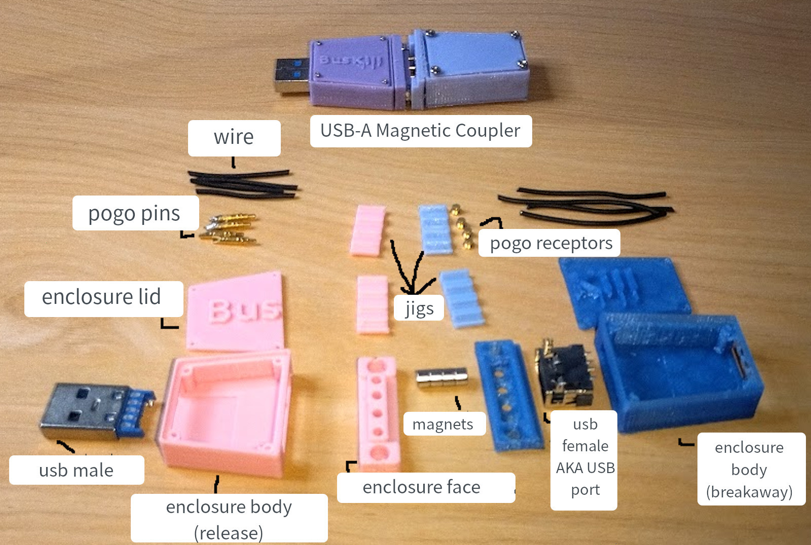
Actually, the best way to confirm the integrity of your hardware is to build it yourself. Fortunately, BusKill doesn’t have any circuit boards, microcontrollers, or silicon; it’s trivial to print your own BusKill cable — which is essentially a USB extension cable with a magnetic breakaway in the middle
Mitigating interdiction via 3D printing is one of many reasons that Melanie Allen has been diligently working on prototyping a 3D-printable BusKill cable this year. In this article, we hope to showcase her progress and provide you with some OpenSCAD and .stl files you can use to build your own version of the prototype, if you want to help us test and improve the design.
ⓘ Note: This post is adapted from its original article on Melanie Allen’s blog.
Demo
In our last update, I showed a video demo where I succesfully triggered a lockscreen using a BusKill prototype without the 3D-printed body for the case and N35 disc magnets. I realized that the N35 disc magnets were not strong enough. In this update, I show a demo with the prototype built inside a 3D-printed case and with (stronger) N42 and N52 cube magnets.
Can’t see video above? Watch it on PeerTube or on YouTube at youtu.be/vFTQatw94VU
What is BusKill?
BusKill is a laptop kill-cord. It’s a USB cable with a magnetic breakaway that you attach to your body and connect to your computer.
If the connection between you to your computer is severed, then your device will lock, shutdown, or shred its encryption keys — thus keeping your encrypted data safe from thieves that steal your device.
Introduction
Thanks to funding from Open Collective, I was able to purchase 16 N42 cube magnets and 16 pogo pins, enough to make 4 prototypes. I also purchased for myself additional N42 and N52 cube magnets for personal experimentation. I was 90% sure that the N42 magnet strength is sufficient, but I wanted to check the difference between the strengths for myself. I had read that N42s are very strong and useful for most applications and that N52 are double the price for only 20% more power.
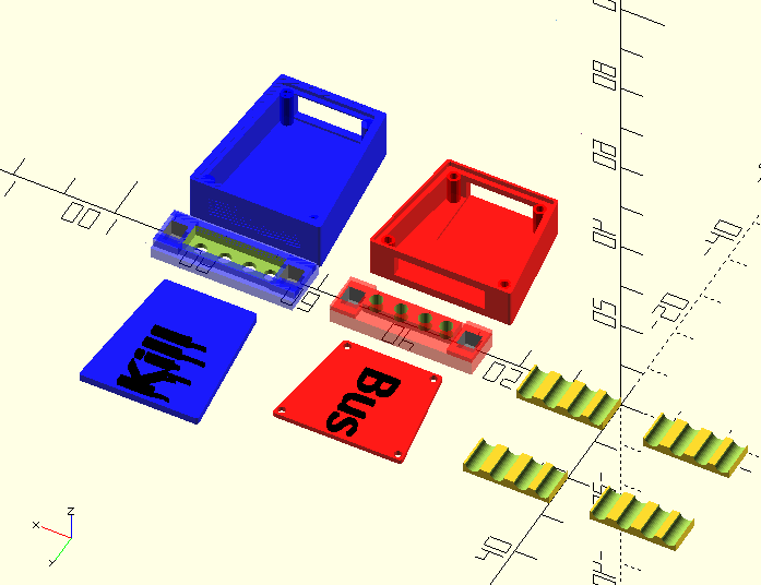
I printed version 3.9.0 of the case (OpenSCAD file, STL file)
I began working on 2 prototypes:
- Gold to test N52 Magnets (get it? gold magnets, gold prototype?)
- Silver to test N42 Magnets and create a demo video
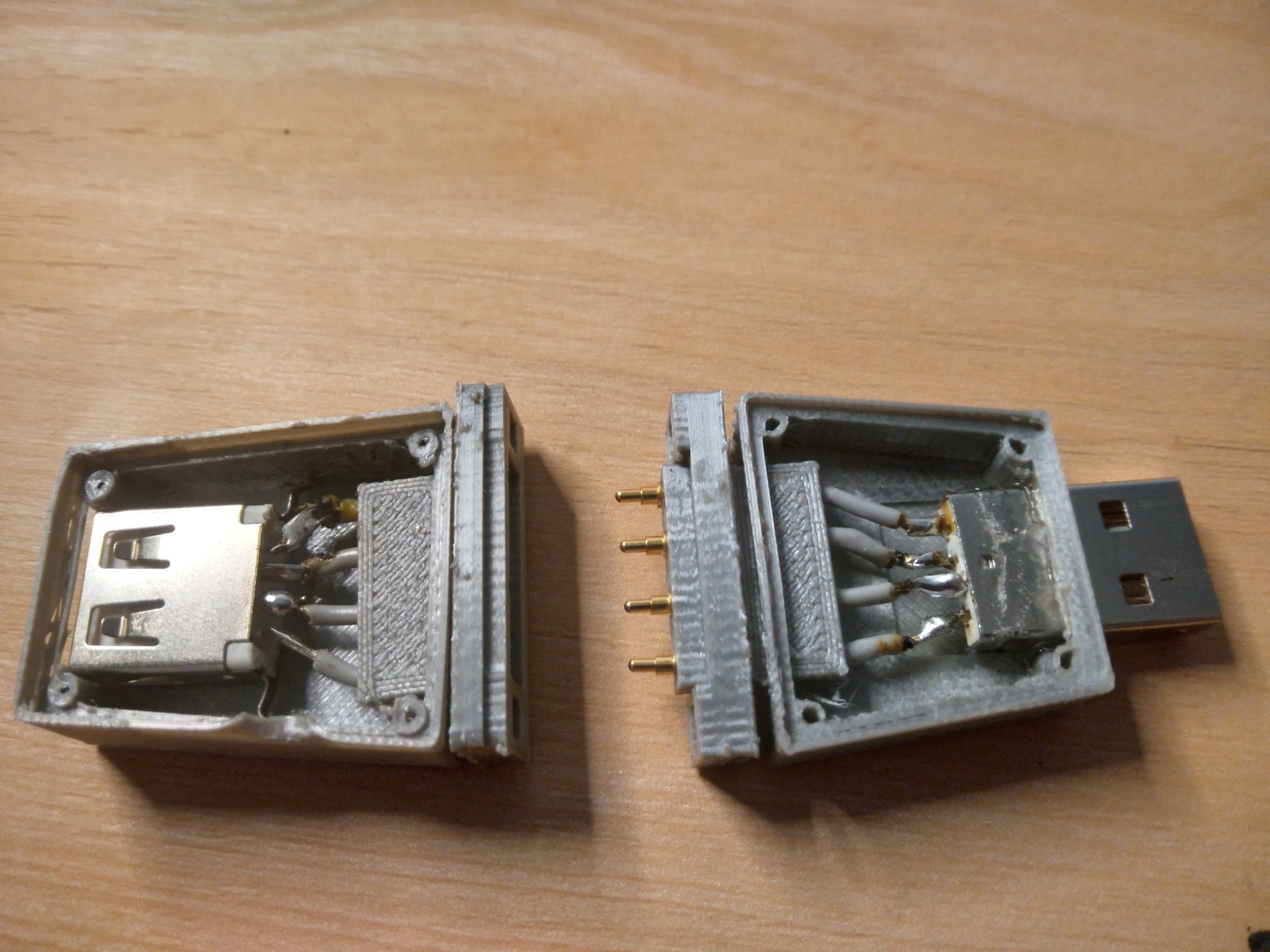
However, while my initial intention was to test the magnet strengths, it didn’t quite turn out that way. I made a mistake while gluing magnets that I couldn’t undo and ended up with two prototypes that had one gold end and one silver end. However, since they differed in how I placed the pogo pins, I was able to use my two prototypes to make progress on that design problem instead.
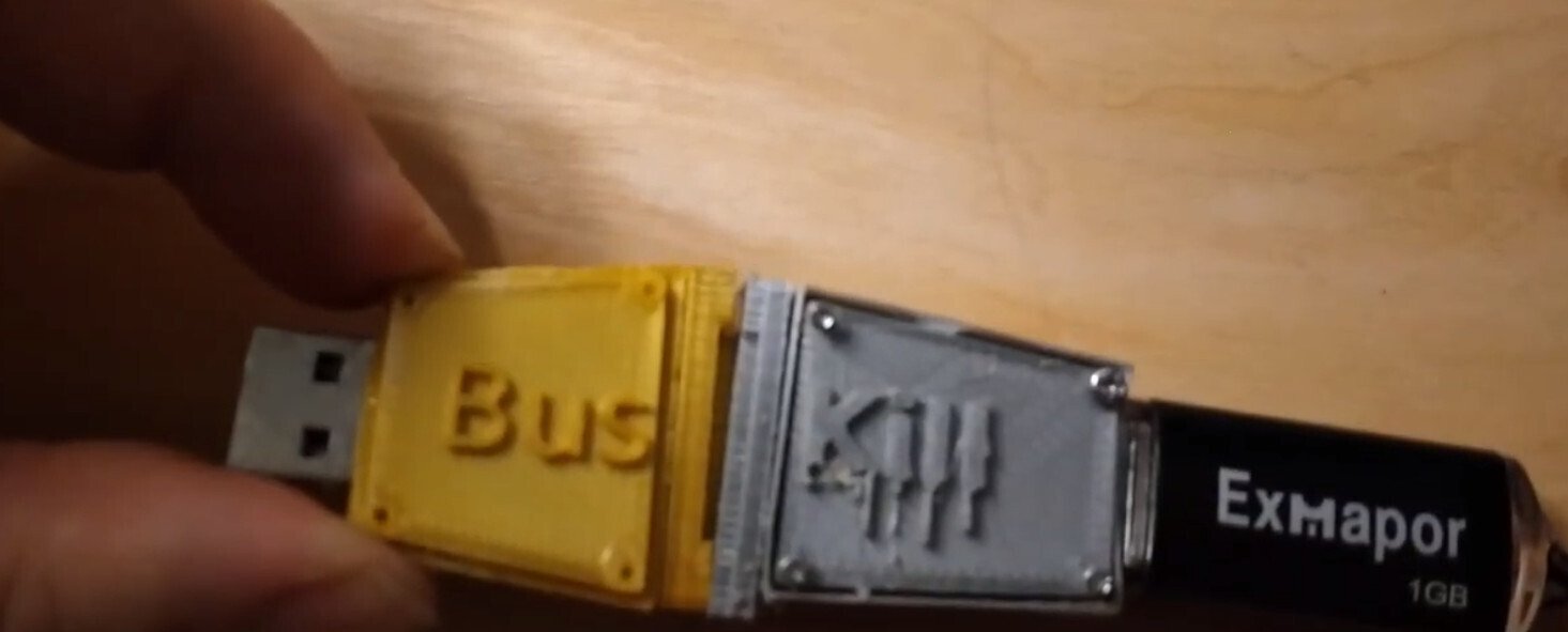
Gold
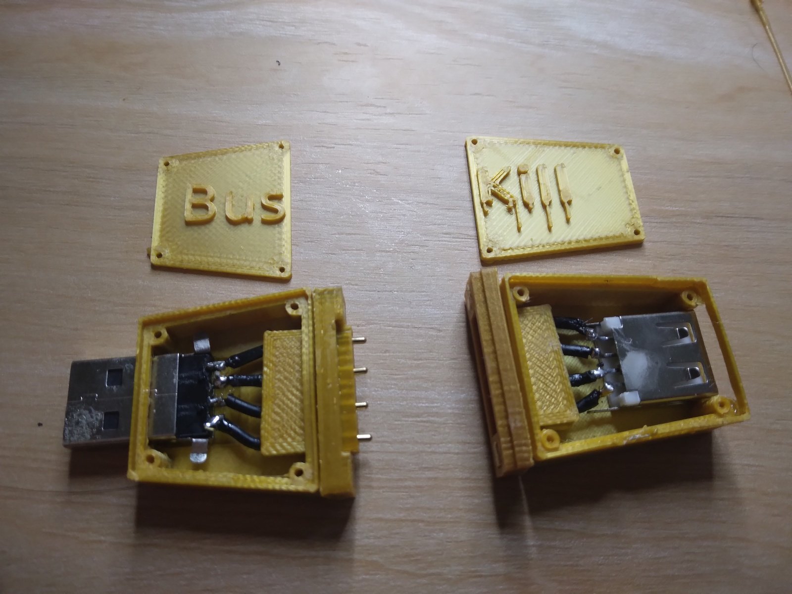
I assembled the gold prototype swiftly. I realized had an incorrect rule of thumb for the orientation of the USB male and USB female hardware in relation to each other. I thought the rule was that both were “upside down” with conductive prongs on top. But this is incorrect, the conductive prongs are placed on top or bottom differently for different USB female hardware.
I learned that this is the rule of thumb: (1) USB male, especially if it does not have prong connections, should be added to the part with the soldering joints facing up (2) USB females usually have prong connections. The USB male and female should not be able to connect. So insert the USB male into the male to double check, and whatever orientation the USB female is in, it should be placed in the opposite orientation during assembly.
Because of my incorrect assumption, once I placed the magnets, the device wanted to magnetically connect in the wrong way. Since I hadn’t yet added magnets to one end of the Silver prototype, I added them so that it would properly connect with the Gold prototype.
This created one functional prototype where I can swap one of the ends out.
Silver
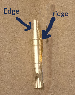
So as mentioned, I had started working on the Silver prototype at the same time as the Gold prototype. I took this opportunity to also test pogo pin positioning. If you look closely at the pogo pins, There is a teeny ridge on them. This ridge is slightly below the edge, a hard surface that the pogo spring collapses into so when the pin is compressed.
With my current the design, the ridge often catches on the top of the hole. However, 3D prints are rarely perfect, there’s usually some issue with at least one of the holes. Nevertheless, it seems beneficial to potentially use this ridge to make assembling easier. But to use this, the part needs to be designed accordingly.
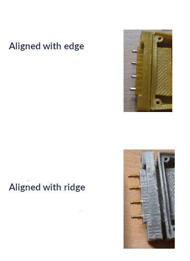
The gold prototype lined up the pogo pins at the edge, the silver prototype lined up the pogo pins at the ridge.
It did appear that the silver prototype has a harder time making the connection. This indicates to me that if I want the pins to line up on the ridge instead of the edge, I should potentially increase the distance of the pogo receptors from the surface.
Next Steps
I want to make some corrections to the 3D model before proceeding and create a version that I’ll use to create written documentation.
- Increase the thickness of the outer walls of the enclosure bodies. Thin is good, but too thin means it’s easy to break during assembly. (If you look closely at IMG 5, you can see that the wall of that prototype has been dented)
- Adjust the placement of the wire channels in the jig pieces – sometimes they’re hard to close over the wires.
- Adjust the distance of the pogo receptors and the pogo pin during connection.
I’m making these changes to version 3.1.
Acknowledgements
I want to give my deepest thanks to those who support BusKill on OpenCollective, who made it possible for me to purchase the materials necessary for this work.
Further Reading
- Original rationale: BusKill hardware wishlist
- For updates and OpenScad & STL files, see the project GitHub Ticket
- Bill of Materials
- Project GitHub Repository
Donate
If you appreciate our progress on 3D-printable BusKill cables, please consider making a donation.
Hardware Development is not free. Expenses to improve this prototype include materials like 3D printing PLA Filament, glue, solder and components like wires, USB ports, pogo pins, magnets etc. All of our expenses are transparently published on Open Collective.
Your contribution (of any amount) is greatly appreciated! Thank you <3
If you’d like to purchase a BusKill cable, click here.