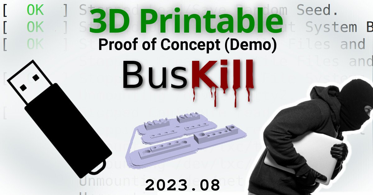
Featured Updates

Bitcoin Black Friday (10% discount on BusKill)
BusKill v0.6.0 released
3D Printable BusKill Prototypes
BusKill Now Shipping!
LUKS Header Shredder (BusKill Self-Destruct Trigger)
previous arrow
next arrow

3D Printable BusKill Prototypes

We're happy to announce that we've had good progress on the design of the 3D printable BusKill USB-A magnetic breakaway couplers this year!

3D Printable BusKill (2023.04)

While we do what we can to allow at-risk folks to purchase BusKill cables anonymously, there is always the risk of interdiction.

We don’t consider hologram stickers or tamper-evident tape/crisps/glitter to be sufficient solutions to supply-chain security. Rather, the solution to these attacks is to build open-source, disassembleable, and easily inspectable hardware whose integrity can be validated without damaging the device and without sophisticated technology.

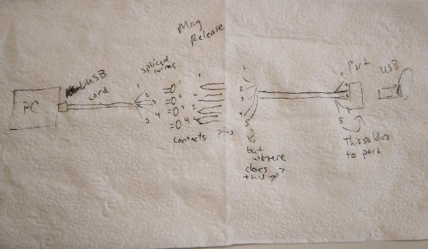
Actually, the best way to confirm the integrity of your hardware is to build it yourself. Fortunately, printing your own circuit boards, microcontroller, or silicon has a steeper learning curve than a BusKill cable -- which is essentially just a USB extension cable with a magnetic breakaway in the middle.

Mitigating interdiction via 3D printing is one of many reasons that Melanie Allen has been diligently working on prototyping a 3D-printable BusKill cable this year. In this article, we hope to showcase her progress and provide you some OpenSCAD and .stl files so you can experiment with building your own and help test and improve our designs.

ⓘ Note: This post is adapted from its original article on Melanie Allen's blog.

Developing the Prototype

Screenshot of a GitHub Issue
The original issue posted in GitHub

Ideation

A few years ago, Michael asked me if I was interested in developing a 3D-printed case for the magnetic breakaway. He enumerated the following design requirements:

  • The case should be as small as possible, because it shouldn’t block neighboring ports, nor sit heavy in the port causing it to bump into objects on the desk.
  • The case should be able to be dissembled, so that people can make sure it isn’t tampered with. It shouldn’t be glued together.
  • In order to avoid using glue, we had a factory specially manufacture some hexagonal shaped magnets that we believed would be able to sit inside the printed part without glue.
  • Much like USB breakaways that are designed to prevent wear and tear on ports, the case would house a pogo pins and magnets, and a USB.
Photo of the design on a napkin
Napkin drawing, when you know its serious

However, over the past years' iterations, we adjusted the requirements:

  • We learned that we didn’t have to put the magnetic release near the port, but that it is better to put it near the person.
  • We realized that these parts are so small (and magnetic), and the magnets so strong, that assembly requires glue. The case itself doen't require glue, but the pogo pins and magnets must be glued in place.
  • Because we are now ok with having to use glue, it is probably better to use easy to find disc magnets rather than the special hexagonal ones.
  • The case doesn’t actually need to house the USB, only the pogo receptors, pogo pins, wires, magnets, and cord.

This process taught me about the realities of going from idea to execution.

My Journey with OpenSCAD

Photo of various 3D printed BusKill prototypes
Pile of test prints of various iterations of the project

When I started this project, I was novice-beginner level with OpenSCAD. I had designed something of similar complexity about 8 years ago. It was a model of an assembly related to creating a timelapse camera for Raspberry PI. I discovered that I had a lot to learn about actually writing good, parametric OpenSCAD code... Even though I commented my BusKill OpenSCAD code thoroughly, it was a mess! It was hard to use myself, let alone sharing with the open source community...

Screenshot shows a 3D model of a 3D Printable BusKill in OpenSCAD
OpenSCAD, the tool I used to design the release case

I had to rewrite it all... sometimes you have to break things to fix them. You have to go backwards to go forwards.

Prototype Begins

And so, chipping away whenever I could -- whether it was few minutes or a few hours -- I am now working on the PROOF OF CONCEPT / 1st Prototype.

And that's what I'm here to share with you today. However, it's still very much a work-in-progress (more on this below).

Current Design

The current prototype design of the 3D printable magnetic breakaway coupler consists of two sides, each of which consist of a top, middle, and bottom. In the OpenSCAD code, the side that would stay with the laptop is called the "release" and the side that would stay with the person is called the "breakaway".

Animated GIF Image shows the explosion of the bottom, middle, and top of the BusKill model in CAD
Both sides of the 3D Printable BusKill coupler have 3 pieces

Tools Used:

Wire stripper, soldering iron with fine tip, helping hands, xacto knife, painters tape, multimeter, alligator clips

Materials Used:

3D printed case (6 pieces), 8 magnets, 4 pogo pins, 4 pogo receptors, solder, wire, usb-to-usb-port cord, usb, carabiner, E360 glue

⚠ WARNING: Many materials used are hazardous, please follow the safety labels if you do this at home. Use proper ventilation, skin, eye, and lung protection when required.

Note: If you can’t acquire a usb-to-usb-port cord, it’s possible to make your own as long as you have a spare usb-to-usb cord and a spare charger that you don’t mind dissembling for this purpose. However, it’s important to make sure that the cord is a data cord, and not a charging cord only. You’ll know because data cords have 4 wires whereas charging-only cords have two wires.

Photo of the 3D printed BusKill
Fresh print of bottom, top, and middle

Print the Case

  1. This prototype uses magnetic_release_B_v0.9.stl. Download from the Github Repository: https://github.com/BusKill/usb-a-magnetic-breakaway
  2. I have a Flashforge Creator Pro and use the Flashforge slicer. I print Hyper Quality and using a raft. Takes about 45 minutes.


ⓘ Note: If you'd prefer to buy a BusKill cable than make your own, you can buy one fully assembled here.

Photo of a USB-A Extension Cable cut in half and stripped
Splice the USB Extension Cable

Assemble the cable

Step 1:

Cut near the port. Splice the wires. Note: cut somewhat close to where the USB attaches to the cord, but not so close that you don't have room for error.

Step 2:

Glue magnets to the middle piece:

  1. Arrange magnets in place Optional: mark the tops and bottoms of the magnet with permanent marker
  2. Apply glue to the middle piece
  3. Slide in the middle piece for one side.
  4. Slide in the middle piece for the other side.
  5. Use a thin but firm material to carefully separate the pieces and allow glue to set.

Tip: I put down a little blue painter’s tape on my workspace where I want to put my pieces down to dry. Also, there’s very little room for plastic-out-of-place and 3D printers don’t always print perfectly. If your magnets aren’t sitting securely, there may be a bit of plastic blocking the way that you need to trim out.

Step 3:

Photo of the pogo pins being soldered to wires
Soldering pogo pins
  1. Solder USB wires to pogo pins
  2. Solder USB wires to pogo receptors

Note: There is a slight asymmetry in the design, you’ll notice a thicker side and a thinner side. This can help you identify if the "top" and "bottom" pieces are oriented correctly.

Tip: I find the original USB wires so tiny and unwieldy that it's difficult to solder them to the even pogos... so I spliced them into breadboard wire first.


Diagram showing the pinout of USB
Pinout diagram I used

Step 4:

  1. Consult pinout diagram to arrange wires correctly.
  2. Use marker to label wire channels in the printed piece.

Step 5:

Glue wires carefully to the top and bottom parts of the case.

The spring part of the pogo pins when pressed should be flushed with the edge of the case, but when not pressed should poke out.

Step 6:

When the glue is dry, sandwich the middle piece between the top and bottom pieces and wrap securely with electrical tape.

NOTE: In the image below the wires are not actually glued yet. I was just sort of mocking it up.

Photo of half of the 3D printed and assembled BusKill coupler
Dry Fit

Where We Are Now

Photo of the spliced BusKill cable connectivity test
Testing the spliced BusKill cable

Before I glued the wires in, I wanted to make sure everything was working and wired correctly.

So I dissembled and attached each wire to itself with alligator clips to test whether my computer would detect it. It failed.

It seemed to me that if this didn’t work then if I proceeded onward it was likely not going to work. I’m a little perplexed. I tried continuity testing, but I'm not sure if my multimeter is faulty..

So I started over again with splicing the cables ... even though I was confident in my soldering work. Yet even without any wires spliced-in ... the wire connected to itself with the alligator clips still isn’t functional. So what is the problem here?

If you have access to a 3D Printer, you have basic EE experience, or you'd like to help us test our 3D printable BusKill prototype, please let us know. The whole is greater than the sum of its parts, and we're eager to finish-off this 3D printable BusKill prototype to help make this security-critical tool accessible to more people world-wide!

If you'd like to purchase a BusKill cable, click here.

Scroll to top